
Choosing an induction hardening inductor style
Induction heat treating coils come in many shapes and sizes, and the style depends on the process. Whatever the style, an inductor must meet the heat treatment specification at the required production rate, tolerate manufacturing variation, mount in the machine, match the power supply electrically, deliver quench, last, run efficiently and repeat from coil to coil. This page summarizes the styles described in the ASM Handbook Volume 4C chapter Design and Fabrication of Inductors for Induction Heat Treating. See Methods for single-shot and scan processes.
Classified by quench delivery
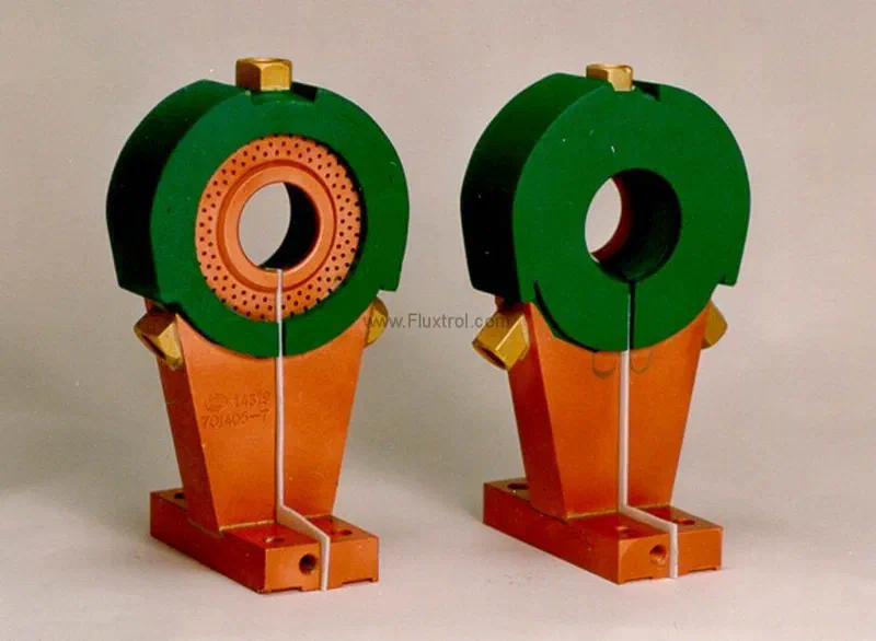
Machined integral quench (MIQ)
An MIQ inductor integrates the quench into the coil. The most common method delivers quench through the copper itself, typically with separate pockets for water cooling and for quench delivery. In some designs it is delivered through the magnetic flux concentrator, which Fluxtrol SMCs allow by machining channels in the material. MIQ coils are built for both single-shot and scanning. Because machined inductors are drawn in CAD and transferred to CAM, complex coils can be made with greater repeatability.
Quench in place
Like MIQ, the quench ring is part of the coil assembly, but it is not an active part of the induction circuit. A typical example is a spindle hardening coil.
Separate quench
The quench is not part of the coil assembly and is often delivered at a different station or position. It is used where a delay between heating and quenching for heat soaking is desirable, and is less common for scanning.
Whatever the style, quench holes should be small, staggered and sized to the shaft diameter and gap, and quench should begin before the surface falls below hardening temperature.
Classified by geometry
Encircling inductors
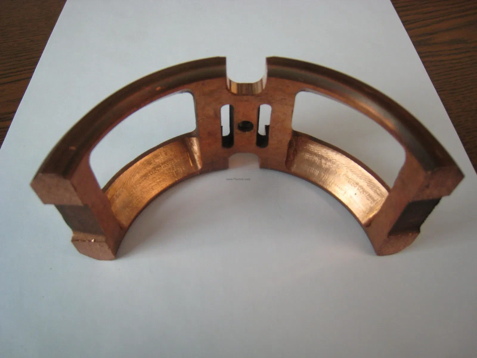
An encircling inductor surrounds the heated section and is used for single shot or scanning. The chapter’s spindle example shows the challenge: current follows the shortest path along the coil inside diameter and the bearing surface, so the coupling gap must vary to compensate, and a single-turn machined coil must balance depth in the fillet against overheating the bearing just above it. For a shorter scanning coil, a flux concentrator drives current down from the shaft into the radius.
Encircling/non-encircling inductors
These combine partial loops with copper rails contoured to the part surface. The part must rotate to heat evenly. Current flows under the loops and follows the rails across the radius, so the end loops control the top and bottom of the pattern and the rails control the central area. For the spindle example, the chapter notes a uniform contour is easier to achieve with a linear inductor than with an encircling one.
Other common styles
Linear, ID, and channel coils are also used. Linear and channel coils are common for scanning, and Fluxtrol’s coil gallery shows ID, channel and crankshaft coils with concentrators.
Structure and support
Low frequency or high power density gives strong electrodynamic forces, so coils need supplemental structure. A support is also needed if the coil is heavy or built from thin-walled tubing. Components include stud boards, retainer rings, mounting plates and connections to quench rings, in most cases made from high-temperature fiber-reinforced plastic. Extreme cases, such as long single-shot axle coils, may add an aluminum housing, taking care to insulate the coil and studs from it.
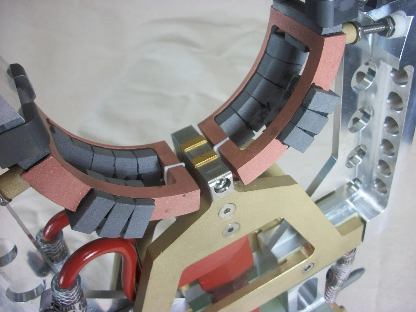
Rotational crankshaft hardening with U-shaped inductors is one of the most demanding. The distance from the transformer to the heating area is long so counterweights clear the transformer, forces act in several directions and reverse as the part passes the Curie point, and the coil touches the part. The structure uses brass or aluminum side plates, ceramic or carbide guide shoes, studs with G-11 components, and sometimes side-support composites for rigidity.
Leads, cooling and flux controllers
Coil leads (busswork) carry the same current as the coil head. Good practice keeps them close with insulation between them, and machined contact blocks with keys are preferred for high power density at low or medium frequency. Copper overheating is the leading cause of failure in heavily loaded inductors, so cooling passages are designed for the power level, and an SMC concentrator can help by cutting coil current. Laminations and SMCs are attached by brazed tabs, epoxy, clamping or fasteners. See Assembling SMCs .
Talk to us about your inductor
Fluxtrol designs, simulates and prototypes heat treating inductors. Contact us or see Induction Coil Design & Engineering .
Flux controllers for heat treating inductors
Inductor designs in the literature
Design and Fabrication of Inductors for Induction Heat Treating
The ASM Handbook Volume 4C chapter by Goldstein, Stuehr and Black covers coil styles, current flow, frequency, structure, quenching, cooling and construction skills.
- Spindle example: encircling vs encircling/non-encircling vs linear
- U-shaped crankshaft coil structure
- Single-shot coil copper temperature case study
Best Practice for Design and Manufacturing of Heat Treating Inductors
ASM HTS 2015 paper on eliminating failure points through design, material selection, cooling and flux control.
- Computer simulation predicts heat patterns and coil temperatures
Optimizing performance of crankshaft hardening inductors
A U-shaped rotational crankshaft coil rebuilt with a machined Fluxtrol A concentrator in place of laminations and keepers.
- Concentrator glued to the winding with epoxy
- Coil lifetime up 100%