
Induction heat treating in brief
Induction heat treating covers hardening, tempering and annealing. It needs simultaneous control of electromagnetic fields, current flow, time and temperature. The usual goal is to heat a specific area of a part, such as a bearing race, journal or tooth flank, quickly above its austenitizing temperature and quench it right away to reach the case depth and hardness profile the specification requires. This page covers the principles; Methods and Inductor Styles apply them.
Current flow and the proximity effect
Eddy currents are the primary source of heat in most induction heat treating applications. Like any current, they must form a closed contour, and in most cases the current in the workpiece follows the shape of the coil because of the proximity effect. Power density at any point depends on current density there, which is shaped by:
- The coupling gap between coil and workpiece
- The width of the copper heat face
- Geometry changes in the part: fillets, undercuts, corners, shoulders, chamfers, splines, keyways and oil holes
- Electromagnetic end and edge effects
- The presence of magnetic flux concentrators
Where current flows perpendicular to a geometry change, it favors the surface closer to the coil. At the end of a closer section, heating rises for a magnetic (hardening) condition and falls for tempering, an electromagnetic end effect whose size depends on frequency. Where current flows along a geometry change, the edge effect is smaller.
Frequency and skin depth
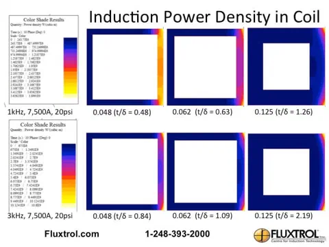
Frequency sets how deep the current and heat penetrate. Practitioners use the reference depth, or skin depth:
skin depth = k x square root of (resistivity / (permeability x frequency))
where k is a constant that depends on units. Depth falls as frequency rises. In large bodies, 63% of the current and 86% of the power lie in the first reference depth.
In hardening, the real distribution differs, because the cold magnetic steel beneath the hot nonmagnetic surface layer still interacts with the field. Practical consequences:
- Lower frequency: higher power, shorter heating time and lower surface temperature for the same case depth; larger electrodynamic forces and a need for robust coil structures.
- Higher frequency: lower power and longer heating time to reach the same depth without overheating the surface; a stronger proximity effect, which helps heat fillets.
Frequency also affects the coil itself. The most effective conductive wall thickness of coil tubing is about 1.6 times the reference depth in the copper; thinner walls cost efficiency, though mechanical practicality often sets a thicker wall. The ASM chapter lists typical wall thickness by frequency, from 0.75-1 mm at 50-450 kHz up to 4-6.5 mm at 1-3 kHz.
Three tools for controlling the heat pattern
Meeting the specified pattern and transition zone is often the hardest part of heat treating. In scan hardening, power and scan speed can be adjusted as the part moves through the coil. In single-shot coils, the pattern has to be designed into the coil using three tools.
1. Coupling gap
The most direct control. A closer coil gives more intense heating because current flows in a narrower band; a larger gap spreads the current over a longer length and lowers power density.
2. Coil copper profile
The part of the coil turn that faces the workpiece and carries most of the current is the heat face. Changing its geometry profiles the power. A common example is a larger gap in the middle of the coil than at the ends, which compensates for flux divergence and thermal losses at the coil ends and keeps the pattern out of an undercut or snap-ring groove. For coils with several heat faces, narrowing the heat face raises power density, though the real effect is much less than ideal theory predicts because not all current is under the heat face (the chapter’s simulation found about 17% rather than 78%).
3. Magnetic flux controllers
This is the most effective and precise method. A soft magnetic composite such as Fluxtrol (or laminations) placed near the coil gives the field a low-reluctance path, concentrating it and driving nearly all current onto the desired heat face. Profiling the SMC poles contours the pattern smoothly through areas such as fillets, without steps in the copper and without excessive heating of adjacent bearing journals.
Coil integrity: quench, cooling and structure
A heat treating inductor must also deliver quench, survive thermal cycling and stay mechanically stable:
- Quench. Quenching is the second half of heat treating. It should be vigorous and uniform, usually through staggered small holes, and should start before the surface cools below hardening temperature. Non-uniform quench causes uneven hardness and distortion.
- Cooling. High currents require water-cooled copper. Copper overheating is the leading cause of failure in heavily loaded inductors, usually as fatigue cracking from thermal cycling. Reducing local power density, for instance by using an SMC concentrator that lowers coil current, extends life.
- Structure. Electrodynamic forces scale with the square of coil current, so low-frequency, high-power coils use fiber-reinforced plastic supports and other structures.
Put the principles to work
Fluxtrol applies these principles with simulation and Fluxtrol SMCs to meet difficult patterns and extend coil life. Contact our team about your hardening application, or return to the induction hardening overview .
Flux controller materials for heat treating coils
Principles in practice
Crankshaft pattern control with copper profiling
A simulation in the ASM Handbook chapter compares a nonrotational crankshaft bearing coil with and without a recessed center. The profiled heat face lengthened the high-temperature zone with a lower maximum surface temperature.
- 50 kHz, 2 mm coupling gap, 4 s heating
- Fluxtrol 50 side plates reduce coupling to the sidewalls
Frequency control in axle scan hardening
Studies at 1 kHz and 3 kHz showed how frequency changes dwell time, the contribution of each coil turn and the limiting factor on scan speed.
- At 3 kHz the proximity effect makes fillet heating easier
- Surface temperature, not power, limits scan speed at 3 kHz